The pulse sensor and Sensorfact Software are designed to continuously register consumption data by monitoring the pulse output of the gas and water. The pulse sensor sends a wireless message to a bridge once it registers a pulse – or - when it does not register any pulse within a single hour. Subsequently, following the correct volume or power coefficient (i.e. # of pulses per mᶟ), the Sensorfact Software logs the data and shows the consumption over time.
There are different methods to connect your meters to the pulse sensor. The suitable method follows from the brand and type of gas meter you have installed. In the connection advice you receive from Sensorfact, the method that works with your meter is explained.
Determine the suitable connection method
There are different methods to connect your meters to the pulse sensor. The suitable method follows from the brand and type of meter you have installed. In the connection advice you receive from Sensorfact, the method that works with your meter is explained.
Meter cable with pulse output (3mm to 6mm)
Already part of your meter

DIN-cable, fitting to your meter’s pulse generating DIN-socket
Delivered by Sensorfact
Selection of 2 Pins to connect, advised by Sensorfact
In case of multiple DIN-sockets, Sensorfact advises which one to use

Pulse generator generating a pulse output signal,often by monitoring the number of rotations of the meter
Brand and type is advised by Sensorfact
If required: selection of 2 Pins to connect, advised by Sensorfact
A Pulse generator comes with a separate manual

Set the settings of the pulse counter
Start by opening the lid of the pulse sensor with a PH2 screwdriver. You will see the below:
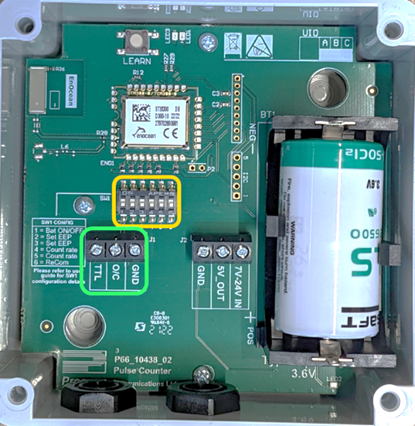
Yellow: DIP-switches
Green: Connection ports
Then, insert and fasten the connection cable. The cable entry glands of the pulse sensor are designed for the entry of a 3mm to 6mm cable, only use the left entry gland. To ensure the sealing effectiveness level (IP classification), ensure that the cable only splits at the inside of the sensor.
- When a DIN-cable or pulse Generator is used, check the connection advice before installation. The advice shows the selected pins to connect to the connectivity ports.
- The pulse counter has 6 DIP switches, which can be accessed and used to configure the device after unscrewing the lid of the pulse counter. After setting the desired configuration, the LEARN button must be pressed for the configuration to take affect.
Each DIP switch can only be ON (up) or OFF (down). Switches can be set by using a small screwdriver or pen to move them up or down.- The DIP switch configuration is as follows:
- The DIP switch configuration is as follows:
This is the configuration for low-speed pulse sources (e.g. meters) which produce pulses at a maximum speed of ≲ 1 per second. If problems are encountered with this configuration, or battery life is a concern, the non-standard configurations should be consulted.
- Medium speed (between 1/s and 6/s):
The DIP switch configuration is as follows:
- The DIP switch configuration is as follows:
- Before inserting, strip the wires/pins to enable connectivity and make sure the gland is fully tightened after inserting the cable.


The selected two pins of the cable should be connected to the terminals marked O/C (Open/Close) and GND (Ground). The polarity/order of the connections does not matter here.
Next, you have to activate power by moving DIP-switch 1. By changing the position of DIP-switch 1 (by moving it upwards), you activate the pulse sensor battery. After doing so, close the lid.
Activate pulse sensor battery

Do not change the position of DIP switch 2 – 6 upwards, unless Sensorfact suggests you do so. These switches can impact the calculation of your data.
Before mounting, check whether the sensor shows as online (green) in the ‘Status’ tab of the software. If the sensor or data is not or incorrectly shown, follow the troubleshooting guide or contact support@sensorfact.nl.
Mounting of the pulse counter
When choosing the location for mounting the sensor, avoid placing the device on a metal surface. This would affect the signal strength between the sensor and the bridges.
The casing of the pulse sensor can be mounted via the outside with the sticky ps and via the inside with the screw kit (which accompanies O-pads for additional IP protection). We recommend mounting it on a vertical non-metallic surface, with the cable entry gland facing downwards. Do not wrap the applied cable around other cables, as this can cause electrical interference to the pulse output.